The Config Tool is available to download for installers that have setup a Pulse-Eight Installer ID for our Monitoring Website at:
https://monitoring.pulse-eight.com/Downloads/ProAudioConfigTool
If you do not already please reach out to your local distributor or Pulse-Eight Sales and Support Agents to issue you with an installer ID and User Auth Code required to register at: https://monitoring.pulse-eight.com/
The ProAudio Config Tool is useful to give an overview of how the ProAudio Matrix is currently configured and makes changes. All changes made will be made in real time, however you will need to backup any settings changed or they will go back to default values when the unit power cycles.
To return the tool to the device list click the icon on the top left of the program.
The Config Tool UI
For this example I have used a ProAudio64
The UI for the ProAudio Config tool will look similar to this:
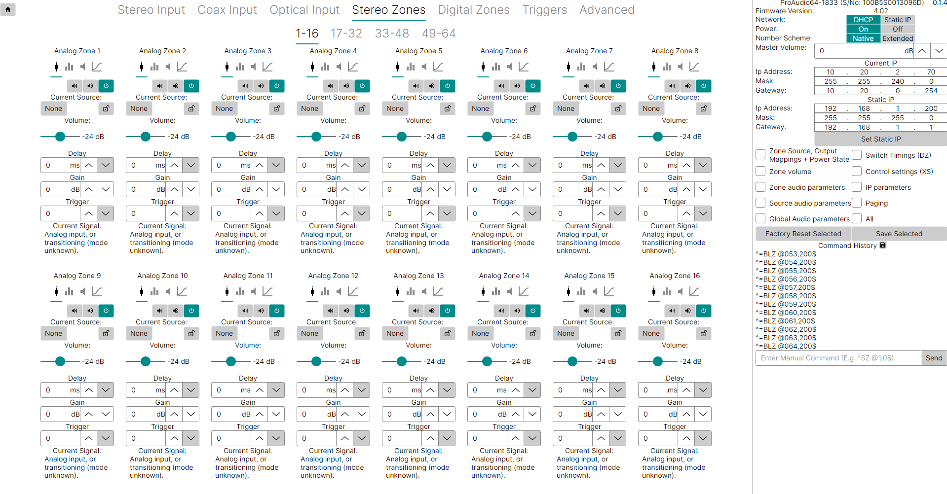
In this Article I will go through the functions and UI section by Section:
The Side Bar:
The side bar will be viewable from any tab of the Config Tool unless toggled away by pressing ctrl+1

System Settings
The top section of the sidebar gives the following information:
- Model of the ProAudio
- Firmware Version
- Whether the Matrix is currently set to DHCP or Static IP, this can be toggled on and off here. (For more information on how to set a Static IP please see the linked Support Article: https://support.pulse-eight.com/a/solutions/articles/30000043687)
- The Power toggle which indicates whether your matrix is currently on or off
- Whether the Matrix is using the Native Number Scheme to this model or is using the Extended Number Scheme required by certain Control Systems, This can be toggled on and off here. (For more information on the Extended I/O please see the linked Support Article: https://support.pulse-eight.com/a/solutions/articles/30000051268)
- The Master Volume in Decibels, this can be adjusted here by either using the up and down arrows or by clicking in the box and typing.

Network Settings
The next section down is used to see the Current IP settings of the Matrix and for setting up Static IP addresses for when Static IP is enabled in the section above.
(For more information on how to set a Static IP please see the linked Support Article: https://support.pulse-eight.com/a/solutions/articles/30000043687)

Factory Reset and Save Settings
The next section down is used for sending Factory Reset and Save Settings commands
To Factory Reset a setting to default tick the relevant box for the setting you would like defaulted. Then click the "Factory Reset Selected" button to reset these to Factory Settings.
To do a full Factory Reset click the "All" box and then "Factory Reset Selected"
To save a setting click the associated tick box and then click Save Settings, a ^SS command will be issued followed by a ^+$ confirmation in the command history to show this has been accepted. If any settings are not saved then these will be reset to default the next time the unit power cycles.

Command History
Finally on the Side Bar is the Command History, the ProAudio Matrix was designed for use with PuTTY to generate commands and the matrix will then send a confirmation to show this has been accepted.
By using the ProAudio Config Tool you no longer need to enter the PuTTY codes from the ProAudio Universal Serial Protocol Guide for most things, however the Config Tool still sends these PuTTY commands and shares the history.
When the Config Tool first connects to the ProAudio you will see the Command History updating where the tool is probing the matrix to generate an accurate UI of the live state of the matrix.
Following this any commands generated from a control system or using the tool itself will generate a command and show the matrix acknowledgement.
This is extremely useful for troubleshooting issues as this updates in real time allowing you to ensure that the matrix is receiving the commands that you expect and to check expected behaviour by referencing these against the Universal Protocol Guide
It is also possible to send PuTTY commands to the matrix by typing them into the box which reads "Enter Manual Command (E.g. ^SZ @1,0$)" and hitting send.

--------------------------------------------------------------------------------------------
Stereo Zones
The first tab that opens when the Config Tool loads is the Stereo Zones Tab
On any matrix with more than 16 zones this will have additional tabs for zone ranges, this is to keep the UI from becoming cluttered.
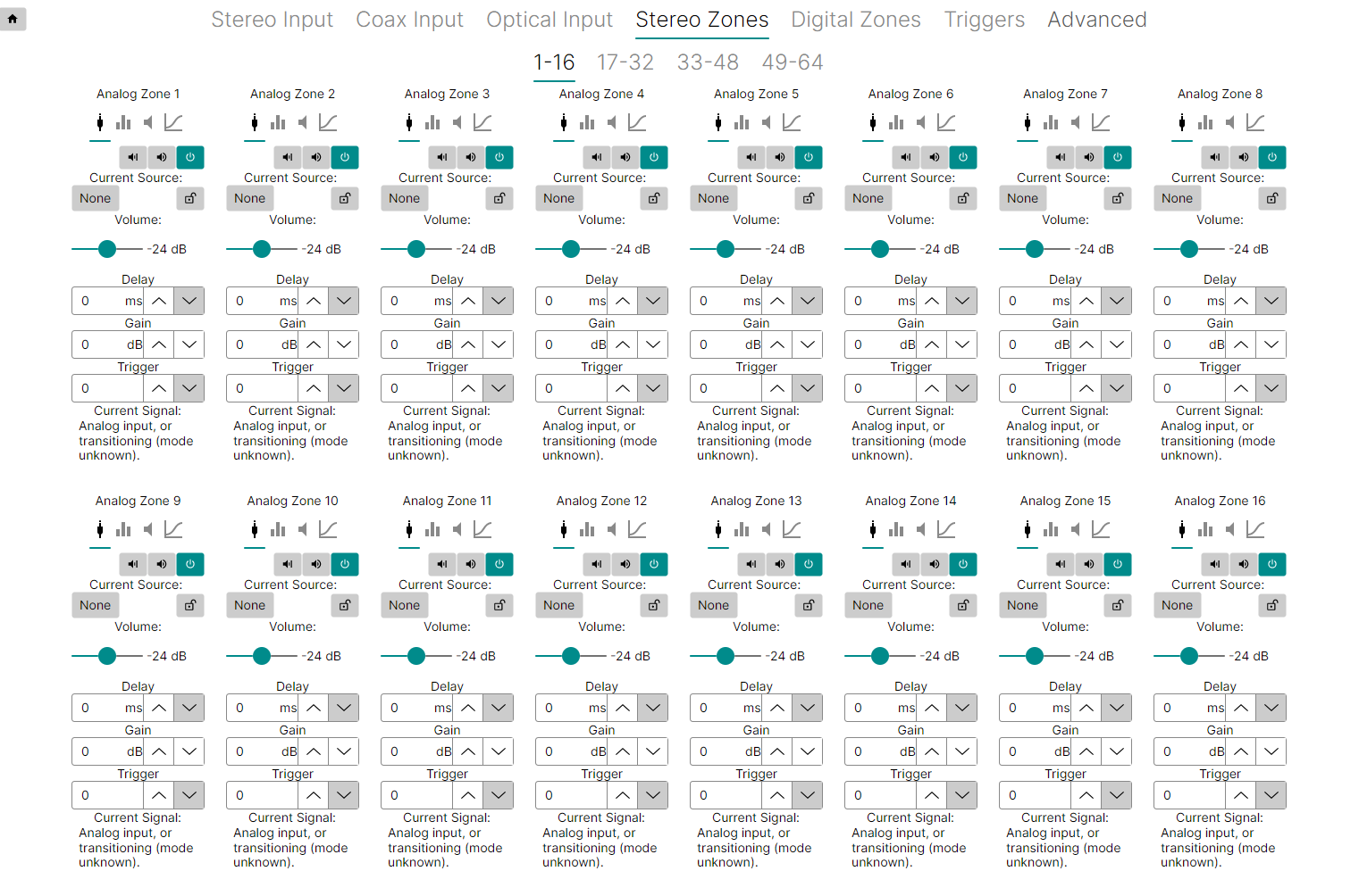
Each zone has its own section, by default the zone will be on the General Tab indicated by this symbol  being underlined.

General Tab
In this tab you will be able to toggle on and off the Hard Mute Setting as well as visually see if this is active.
This is the command used to hard mute, or disconnect an audio zone. When audio is disconnected, the sound is immediately switched off. This command should not be used to simply mute audio on a zone. This command is nearly equivalent to setting a zone to source 0. It disconnects the zone from anything.
If Hard Mute is active the symbol will appear black on a grey background
If Hard Mute is off the symbol will appear white with a cross through on a green background 
Next to the Hard Mute Setting is the Soft Mute Setting similar to the Hard Mute you can toggle this and visually see if this is active.
The Soft Mute Setting allows you to mute the volume on the switch using the audio processor. This is the proper command to mute the audio of the switch. This differs from the Hard Mute Setting which is used to completely shut down, or disconnect a zone.
If Soft Mute is off the symbol will appear black on a grey background with sound waves shown
If Soft Mute is active the symbol will appear white on a green background with a cross replacing the sound waves 
Finally on this line is the Zone Power Setting which again can be toggled to power on and off the zone.
If the zone is not powered then no audio will be passed.
If the Zone is powered the symbol will appear white on a green background 
If the Zone is off the symbol will appear black on a grey background 
The next setting is for Current Sources, here you can route the input you would like to this output by clicking the box indicated, please note that in this example I am not currently routing any audio, if a source is currently set it will read here instead.

This will take you to a list of all the Matrix Inputs and allow you to select which one to route to this output as well as the options of "None" for No Route and "Cancel Selection" if you do not wish to make a change.

to the right of this is a padlock symbol this is used to setup Zone Locking for when you want to lock multiple zones together. For more information see the linked support article: https://support.pulse-eight.com/a/solutions/articles/30000052292
Below this is a volume slide to set the output volume used to make the zone louder or quieter.

The next box down is for the Lip Sync Delay, There are two forms of the lip sync delay, this one on the Stereo Zones Page sets lip sync delay on a zone by zone basis, the other is set on the audio input which sets delays on a source by source basis. Which one to use depends on what is causing the video delay, and where it’s connected in the video path.
If the source of a video processor (or monitor) that adds a video delay is connected to a zone, then using the delay on the Stereo Zone Tab should be used to delay the audio by the same amount of time the video is being delayed.
Only audio that is being sent to the video processor, attached to the zone, will be delayed.
On the other hand, if the output of a video processor that adds a video delay, is connected to an input source, then the delay setting in the relevant Input Tab should be used.
This allows all zones that connect to the video processor, to have their delays automatically adjusted to compensate for the processor’s video delays. Both sources and zones can have delays set, however the overall delay cannot exceed 170.65mS.
If a source and zone combination exceeds 170.65mS, no error will be generated and the delay will be set to 170.65mS instead.
The delay can be set either by typing the number directly into the box or stepped up and down using the corresponding up and down arrows which will add a 0.02mS delay for each click.

The box below this is for the Output Gain, each zone has a gain level that can be set from -24 dB to +24 dB. The gain control allows you to match the volume levels of each zone to the sensitivity of the amplifiers used in each zone. This allows volume settings to sound the same for each zone, even when using different model/brand of amplifiers or different model/brand of speakers.
The gain can be set either by typing the number directly into the box or stepped up and down using the corresponding up and down arrows which will add 0.5dB to the output gain for each click.

The final adjustable setting on this tab is to assign a 12V Trigger to the output zone. This box can be used to link the analogue output to a trigger output. The Trigger Output is set by typing the number of the corresponding output in the box or by using the up and down arrows to set the number: For more information on setting up 12V triggers please see the linked support article: https://support.pulse-eight.com/a/solutions/articles/30000052306

Equalizer Tab
The tab to the right of the General Tab is the EQ (Equalizer) Tab and can be accessed by clicking this symbol on the corresponding output
The equalization tab consists of a series of sliding bars where you can set a variety of different Audio Settings and will look like the image below.
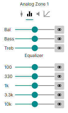
These sliders are used to adjust standard EQ settings, these should seem self explanatory however if you are unsure you can look up online what all these settings do to the music. Changing these settings should not cause any issues to the matrix and it is recommended to play around with the settings to get the correct feel for the space you are in with the equipment that you are using. If you would like to set any of the settings back to default click the  button next to the slider.
Levels Tab
The next tab on this section is the levels tab and can be accessed by clicking the symbol
The levels tab can be used to set the volume levels of the output and the tab will look like the image below.

The Minimum Volume allows you to set the volume to just below the noise level of a quiet room. The volume setting switch can be adjusted down to -99.5 dB before muting. This is usually quite a bit beyond the noise level of any room, or the noise level of most amplifiers. Since adjusting the volume below the noise level is just a waste of time, the minimum level allows you to limit the volume range. Attempting to set the volume below the minimum level will cause the switch go into full mute (no sound). When adjusting the volume upward from full mute, the volume will immediately jump to the minimum level.
Minimum Volume can be set by clicking in the box and entering the desired number in decibels or adjusted in 0.5dB increments using the up and down arrows.
The Maximum Volume prevents a user from overdriving the speakers, amplifier, or even the switch. Setting the volume above the maximum level is not allowed, and will be limited to the maximum volume set by this slider.
The Mute Level allows you to set a mute level from 0 - 248(0 no muting, 248 is maximum). The mute level control allows you to reduce the volume levels of each zone. This allows volume level to be subtracted from the current volume level.
The Mute Level Mode setting affects how the matrix will act when a mute command is sent. When set to Jump the matrix will immediately change to the mute level when the command is set. On Timed it will change over a set time scale. On Sloped the volume will gradually fade out when the command is received and fade back in when the mute is cancelled.
--------------------------------------------------------------------------------------------
Digital Zones
On any matrix with more than 32 zones this will have additional tabs for zone ranges, this is to keep the UI from becoming cluttered.

The Digital Zones tab works in a similar way to the Stereo Zones Tab where it displays a group of zones with the relevant settings available.
Each zone should look like the image below, as is quite quickly apparent there are less adjustable settings for digital zones.

The first setting is the Hard Mute toggle which functions the same as on the Analogue Outputs.
This is the command used to hard mute, or disconnect an audio zone. When audio is disconnected, the sound is immediately switched off. This command should not be used to simply mute audio on a zone. This command is nearly equivalent to setting a zone to source 0. It disconnects the zone from anything.
If Hard Mute is active the symbol will appear black on a grey background
If Hard Mute is off the symbol will appear white with a cross through on a green background 
The next setting is for selecting Input, here you can route the input you would like to this output by clicking the box indicated, please note that in this example I am not currently routing any audio, if a source is currently set it will read here instead.
 This will take you to a list of all the Matrix Inputs and allow you to select which one to route to this output as well as the options of "None" for No Route and "Cancel Selection" if you do not wish to make a change.

Finally on this section is the Audio Routing Settings, by default the zone will be on independent routing, you are able to switch it here to mirror analog zone this allows you to connect it to the analog output of its associated zone.
When used as an independent switch, the Matrix will use a ‘Digital Set Zone’ command to switch between all the digital sources. All digital audio is passed through the switch untouched. This includes Dolby 5.1 and DTS audio. However, you cannot switch the coax output to any analog audio sources’.
When connected to an associated analog zone, the setting of the ‘Digital Set Zone’ command is ignored, and all analog audio from the associated analog zone will be converted to PCM stereo and sent to the coax audio output.
Instead of using the 'Digital Set Zone' command the analogue zone's commands are used to switch between the sources. The coax outputs will mirror the analog zones.
The associated analog zone for each coax is the matching analog zone number. Coax output 1’s associated zone is analog output 1. Coax 2, associates with analog output 2, etc

--------------------------------------------------------------------------------------------
Stereo Input and Coax Input
The Stereo Input Tab and Coax Input Tab are used for making adjustments to the audio and will affect all outputs using that input as opposed to the Stereo and Coax Zones Tabs where you are adjusting individual outputs.

Each Audio Input has three settings that can be adjusted:
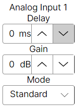
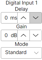
Input Delay: There are two forms of the lip sync delay, this one on the Stereo and Coax Input Tab sets lip sync delay across all of the outputs using this audio on a source by source basis, the other is set on the Stereo Zones Tab which sets delays on a zone by zone basis. Which one to use depends on what is causing the video delay, and where it’s connected in the video path.
If the source of a video processor (or monitor) that adds a video delay is connected to a zone, then using the delay on the Stereo Zone Tab should be used to delay the audio by the same amount of time the video is being delayed.
Only audio that is being sent to the video processor, attached to the zone, will be delayed.
On the other hand, if the output of a video processor that adds a video delay, is connected to an input source, then the delay setting in the Stereo Input Tab should be used.
This allows all zones that connect to the video processor, to have their delays automatically adjusted to compensate for the processor’s video delays. Both sources and zones can have delays set, however the overall delay cannot exceed 170.65mS.
If a source and zone combination exceeds 170.65mS, no error will be generated and the delay will be set to 170.65mS instead.
The delay can be set either by typing the number directly into the box or stepped up and down using the corresponding up and down arrows which will add a 0.02mS delay for each click.

Gain: Each source has a gain level that can be set from -24 dB to +24 dB. The gain control allows you to match the volume levels of each source to the different levels of each source. This allows volume settings to sound the same, when switching between source devices with different output levels.
The gain can be set either by typing the number directly into the box or stepped up and down using the corresponding up and down arrows which will add 0.5dB to the output gain for each click.

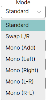
Mode: This setting is used to change how the audio can be mixed in a number of different ways. This includes swapping channels, and a number of ways of creating mono audio.
--------------------------------------------------------------------------------------------
Triggers
The Triggers tab has already been touched on in the 'Stereo Zones' section.
For more information on setting up 12V triggers please see the linked support article: https://support.pulse-eight.com/a/solutions/articles/30000052306
--------------------------------------------------------------------------------------------
Advanced
The Advanced Tab is used to set a variety of different flags that affect how the matrix operates as well as several setting such as Front LED panel lights and brightness.
The current state of the available flags is shown here for debugging purposes. Under normal circumstances these do not need to be changed.

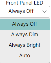
To the top right of this tab is the Front Panel LED control box, using this box you are able to change the look of the LEDs on the front of the matrix
The first LED settings box allows you to set your LEDs to one of 4 presets,
Always Off: Turns off the LEDs
Always Dim: Keeps the LEDs active but at a lower level
Always Bright: Keeps the LEDs active at a higher level
Auto will change the LED state automatically between the three
The first toggle is labelled XIO: this toggle is for enabling and disabling Extended I/O mode, this flag is necessary when using certain control systems, check the driver readme to verify if this is required.
In the Extended I/O mode, all switches use the same mappings for the sources. Setting a zone to a source that doesn’t exist, (like setting a zone to analog input 17, on a switch with only 16 analog inputs) will simply mute the zone - it’s the same as setting the zone to 0.

The second toggle is labelled CRE: This as stated toggles whether the command history ends all responses with a carriage return and line feed.
A carriage return and line feed can be appended to all responses coming from the switch. This is useful when using terminal software to test command strings. Since the carriage returns and line feeds are sent outside of the normal string (they are sent after the ending ‘$’), they should be ignored by the controller. But if there are problems with this behavior, they can be turned off by setting this toggle off.

The third toggle is labelled ECO: This causes the command history to always send a response string when a serial command is issued. ECO is required for this tool to function.
Each command that makes a change to a parameter, will be echoed with a response string that indicates the new values of the parameters changed. The response strings are only issued after the changes have taken affect, and reflect the new state of the switch. With this toggle turned off, these automatic response strings will not be sent.
However if the new parameter is different than the current parameter, and the ‘ASY’ toggle is set, then a response string will still be sent to indicate a parameter has changed.
This flag forces a response string to be sent even if the parameter of the command being sent is the same as the current value of the switch. To stop all response strings from being sent, set this ‘ASY toggle to off.

The forth toggle is labelled ACK: This flag causes the command history to acknowledge error free commands with "^+$".
Each time a command is sent to the switch, the switch responds with either an error message, if there was a problem with the command, or an acknowledgement string of “^+$”. This behavior can be changed by setting this toggle to off. If the bit is set to off, the “^+$” string will not be sent.

The fifth toggle is labelled ASY: This sends a command string on any parameter is changed when activated.
For instance any changes to the front panel will cause a response string to be sent to the serial ports, and any open TCP/IP socket.
With this flag toggled off, response strings are only sent when requested, using the ‘?’ as a parameter. For one way serial control, this flag, and the ‘ECO’ flag could be set to off for faster command history responses times. If a lot of commands are being sent, the response time of the switch can slow down waiting for all the response strings to be sent.

The sixth toggle is labelled MJP: When this toggle is set to off incrementing/decrementing the volume of a muted zone will cause the zone’s volume to increment/decrement from the current muted level.
This is the “no surprises” mode of operation. If one person mutes a zone and walks out of the room, someone else can walk into the room and pick up the volume control and start adjusting the volume with no surprises. The volume will simply start increasing from the current level.
When this toggle is set to on then incrementing the volume of a muted zone will cause the zone’s volume to jump back to its unmuted level before incrementing the level.
This mode is most useful when only one person is in control of the volume. For instance if the phone rings, the mute button can be pressed. Once the call is over, pressing any volume button will cause the volume to jump back to it’s previous setting.

The final toggle is labelled UVL: with this flag enabled the matrix will unmute the output selected if it receives a volume change command.
Control systems that use sliding touch pads will usually precalculate a volume, and send the volume using a ‘VZ’ or ‘VPZ’ volume command without the ‘+’ or ‘-’ characters. If the zone is muted, then the commands will have no affect on the volume, until the zone is manually unmuted.
Setting this flag on causes the zone to unmute whenever one of these ‘VZ’ or ‘VPZ’ volume commands are sent, regardless of whether it’s an incremental command or an absolute volume setting. If, for some reason, you need to send precalculated volume settings to the switch, without unmuting the zone’s volume, then you will want this toggled to off.

Finally there is a button that reads "Set to Suggested" clicking this will set all flags to recommended states. This may not be the best options for your specific setup and you should consider each flags functionality to your specific install.

Was this article helpful?
That’s Great!
Thank you for your feedback
Sorry! We couldn't be helpful
Thank you for your feedback
Feedback sent
We appreciate your effort and will try to fix the article